 |
Most HF amateur stations are equipped with some sort of RF power meter. The "SWR/power" meter is a popular instrument, and is also relatively inexpensive. It is basically a reflectometer in a metal case, with a meter (switchable or crossed-needle) which reads the DC output voltage of the reflectometer's forward and reflected power pickups.
These meters are usually designed for Zo = 50Ω. They will read power accurately only if terminated in 50Ω resistive.
The HF operator may wish to calibrate his SWR/power meter against an absolute power-measurement standard from time to time. Laboratory standards are very costly, and even an accurate commercial meter such as the Bird 43 represents a significant outlay.
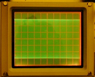
If an accurate 50Ω dummy load is available in the shack, we can measure RF power by measuring the RF voltage developed across the load. If a calibrated oscilloscope is available, we can connect our 10X scope probe across the dummy load, apply a CW signal from the transmitter, and measure the peak-to-peak voltage Vp-p. A typical oscilloscope display is shown in Fig. 1.
 |
The peak-to-peak voltage is 2.828 times the root-mean-square (rms) voltage. Vp-p = 2.828 * Vrms, so Vrms = 0.3535 * Vp-p.
Average power Pav = (Vrms)2 ÷ R
Pav is expressed in watts. (Note: We are measuring the average power of a CW signal. "RMS power" is a misnomer!)
For example, if the oscilloscope reads 20V p-p with a 10X probe, Vp-p = 20 * 10 = 200V.
Thus, Vrms = 0.3535 * 200 = 70.7V
Pav = (70.7)2 ÷ 50 = 100W.
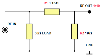
A 10:1 resistive voltage divider may be connected between the dummy load and the oscilloscope probe to reduce the RF voltage applied to the probe, as shown in Fig. 2. The resistors should be non-inductive, and of adequate power rating.
 |
In the example shown in Fig. 2, R1 = 9.1kΩ and R2 = 1kΩ. At 100W in 50Ω, the power dissipated in R1 + R2 is (70.7)2 ÷ 10000 = 0.5W. (P = V2 ÷ R). Thus, R1 and R2 should be 1W and 0.25W metal-film, respectively. Leads should be kept as short as possible. The scope probe should be connected directly to RF OUT to minimise stray capacitance, which will otherwise attenuate the signal sample and cause measurement errors.
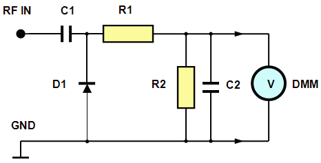
A simple diode probe connected to a digital multimeter (DMM) is a reasonably accurate alternative if an oscilloscope is not available. Fig. 3 is a schematic of a typical probe.
 |
| C1: 1nF 1kV. C2: 10nF 100V. R1: 470KΩ ¼W. R2: 1.1MΩ ¼W. D1: See text. |
The diode probe is a half-wave peak rectifier; its output voltage is equal to the peak value of the applied RF voltage, less the diode barrier voltage. To minimise the diode drop, D1 should be a germanium diode such as 1N34A, OA90 or OA91. These diodes have a barrier voltage of approx. 0.25V vs. 0.4V for a Schottky diode (e.g. 1N5711) or 0.7V for a silicon diode (e.g. 1N4148). The OA91 has 115V PIV, but may be difficult to locate. A 1N5711 Schottky diode (PIV = 70V) may also be used for D1.
A silicon diode such as the 1N4148 is not recommended, as its higher barrier voltage will introduce greater error at low power levels.
Assuming that D1 is a 1N34A, the applied peak RF voltage is equal to the DC output voltage + 0.25V.
Thus, Vpk = (Vdc + 0.25) volts, or Vdc = (Vpk - 0.25) volts.
As for the oscilloscope case:
Average power Pav = (Vrms)2 ÷ R = (0.707 Vpk)2 ÷ R = ( Vpk)2 ÷ 2R
Thus, Pav = ( Vdc + 0.25)2 ÷ 2R
Example: Vdc = 20V, R = 50Ω. Pav = [(20.25)2 ÷ (50 * 2)] = 4.1W
In Fig. 3, R1 = 470kΩ, and R2 = 1.1MΩ. These resistor values provide scaling from peak to RMS for a sine-wave input. A DMM with Zin > 10 MΩ will not significantly load down the probe. The DMM reads 0.7 * Vdc or 0.7 * ( Vpk - 0.25), which is pretty close to Vrms.
For the above example, if Pav = 4.1W, Vpk = 20.25V, and the DMM will read 14V. (Vrms = 0.707 * 20.25 = 14.3V).
Because of the PIV limitations of the diodes, the 10:1 voltage divider (Fig. 2) must be placed between the 50Ω dummy load and the probe for higher power readings.
Example:For Pav = 100W, Vrms = (PR)½ = (100 * 50)½ = 70.7V
Vpk = 1.414 * 70.7 = 100V. The divider ratio is 10:1. Thus, Vpk = 10V at the probe input. The DMM will read 0.7 * (10 - 0.25) = 6.8V
The probe should be built into a metallic shielding enclosure. Leads should be kept as short as possible.
For those who would prefer to purchase and build a kit, Elecraft offers an RF probe kit for $10.00 under their order code RFPROBE.
"RMS Power", by Roy Lewallen W7EL (PDF)
"What's RMS Power or RMS Watts?" by Paul Quillen N4LCD (PDF)
Copyright © 2009 A. Farson VA7OJ/AB4OJ, including images. Last updated: 09/25/2019