|
|
Connecting the Yaesu Quadra (VL-1000) to an Icom or Kenwood* Exciter |
|---|
(*Kenwood TS-590S/SG, TS-890S, TS-990S)1. Connecting the Quadra to an Icom Exciter: |
|
|
Reprogram the Quadra amplifier per Yaesu's instructions, to activate 10 and 12m; this reconfigures the amplifier as the "International" model.
On the exciter, set the RF POWER control to 75W. The VL-1000 requires at least 75W of drive for correct auto-tuning or bandswitching.
On Icom exciters with the TX Delay menu item (IC-7100, IC-7300, IC-7600/7700/7800 with recent firmware, IC-7850/51, IC-7610) set HF TX Delay and 50M TX Delay to 10 ms.
Set the REMOTE switch on the VL-1000 rear panel to OFF (down).
If remote power on/off switching from the exciter is desired, connect Band Data 2, Pin 1 (+13.6V) to ACC2 Pin 7 (13.8V) as illustrated here. Set the REMOTE switch on the VL-1000 rear panel to ON (up).![]() WARNING! Do not short-circuit or ground ACC2 Pin 7, or severe damage to the Icom exciter will result.
WARNING! Do not short-circuit or ground ACC2 Pin 7, or severe damage to the Icom exciter will result.
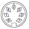
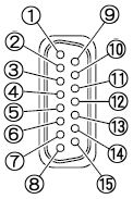
Connect the Quadra to the Icom exciter, via 4 cables: RF, ALC (mandatory), PTT and remote keying interface. The latter allows the Quadra to key the exciter for tuning when the F.SET or TUNE button is pressed. The remote keying interface cable is a shielded cable which connects VL-1000 Amplifier Band Data 2 (DB15) to Icom ACC2 (7-pin DIN). Connect Band Data 2, Pin 9 (F SET COMMON) via shield to ACC2 Pin 2 (GND). Connect Band Data 2, Pin 11 (F SET 2) via center conductor to ACC2 Pin 3 (SEND). See Figure 1 above. The Band Data 2 cable supplied with the Quadra can be modified for this purose, or a female RCA/male 7-pin DIN pigtail can be made up to connect the Band Data 2 cable to ACC2 Pin 3.
![]() If the Icom exciter has a 13-pin DIN ACC socket, connect VL-1000 Amplifier Band Data 2 (DB15) Pins 9 and 11 to Icom ACC (13-pin DIN) Pins 2 and 3 respectively.
If the Icom exciter has a 13-pin DIN ACC socket, connect VL-1000 Amplifier Band Data 2 (DB15) Pins 9 and 11 to Icom ACC (13-pin DIN) Pins 2 and 3 respectively.
Connect the ALC cable from the ALC 1 jack on the VL-1000 to the ALC jack on the Icom exciter. Connect the PTT cable from the PTT 1 jack on the VL-1000 to the SEND or RELAY jack on the Icom exciter. (Note: If the exciter is an IC-7600, IC-7610, IC-7700, IC-7800 or IC-7850/7851, set SEND Relay Type to MOS-FET in ACC set menu.)
Prior to pressing F.SET or TUNE, set the exciter to RTTY or FM mode to transmit a continuous carrier to the Quadra. When the bandswitching or auto-tuning cycle is complete, select the desired operating mode.
ALC calibration: Set the Quadra's ALC level to limit power output to 1 kW, corresponding to approximately 80W of drive. It is sufficient to calibrate the ALC on one band; the power output is almost constant across all HF bands. (Note: If the exciter power output can exceed 100W, as is the case for the IC-775, IC-781, IC-7700, IC-7800 and IC-7850/51, the input attenuator ATT should be enabled). Refer to VL-1000 User Manual, p. 12. The Quadra's ALC line is compatible with that of an Icom exciter (0 to -10V DC). The typical ALC voltage for 1 kW output is about -4V DC.
The RF input impedance of the Quadra is 50 ohms resistive (frequency-independent). It is therefore unnecessary to engage the transceiverís autotuner when driving the Quadra.
Note: As Icom exciters do not support the Yaesu Band Data 1 cable, the following Quadra features are not available in this configuration:
The GND, PTT2, ALC2 and Band Data 2 leads from the Quadra are connected to a 7-pin male DIN plug per Table 1. The plug is inserted in the REMOTE socket on the rear panel of the TS-590 orTS-990. (PTT1 and ALC1 can be used instead if desired.)
The coax jumper is connected between the exciter's antenna socket and either INPUT 1 or 2. The PTT and ALC connections must match the selected INPUT.
| Quadra | REMOTE | Pin |  |
|---|---|---|---|
| NC | SPO | 1 | |
| GND, Band Data 2 Pin 9 | COM | 2 | |
| Band Data 2 Pin 11 | SS | 3 | |
| PTT2 (RCA) | MKE | 4 | |
| NC | BRK | 5 | |
| ALC2 (RCA) | ALC | 6 | |
| NC | RL/LKY | 7 |
Note that REMOTE Pin 2 (COMmon) is connected to the shields of the RCA-ended PTT2 and ALC2 cables and to Band Data 2 Pin 9, as shown in Fig.1 above.
Alternatively, a cable can be made up per Table 2 if interfacing to the Quadra via Band Data 2 and Input 2 is acceptable. ALC (Kenwood REMOTE Pin 6) is connected to a shielded RCA plug-ended pigtail, which is plugged into Quadra ALC2.
The coax jumper is connected between the exciter's antenna socket and INPUT 2.
 | Quadra Band Data 2 | Pin | Kenwood REMOTE | Pin |  |
|---|---|---|---|---|---|
| NC | SPO | 1 | |||
| GND | 3, 9 | COM | 2 | ||
| F SET 2 | 11 | SS | 3 | ||
| TX GND | 2 | MKE | 4 | ||
| NC | BRK | 5 | |||
| ALC2 (RCA) | ALC | 6 | |||
| NC | RL/LKY | 7 | |||
| Connectors viewed from rear panel | |||||
Note that REMOTE Pin 2 (COMmon) is connected to the shield of the RCA-ended ALC2 pigtail and to Band Data 2 Pins 3 & 9.
Operation of the Quadra with the TS-590S/SG is identical to that with an Icom exciter. The TS-590S/SG or TS-990S RTTY key is labelled FSK.
![]() Do not exceed 75W drive power.
Do not exceed 75W drive power.
Copyright © 2002-2022 A. Farson VA7OJ/AB4OJ. All rights reserved. LLast updated 11/20/22.