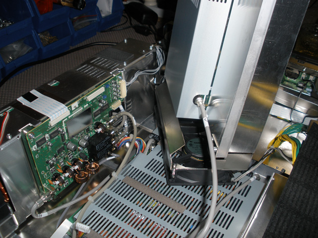
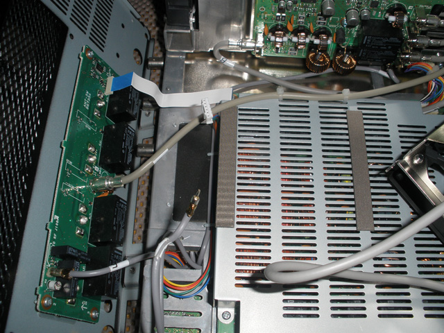
Remove both the top and bottom covers and place them aside where they will not fall or be scratched. On the bottom of the radio is a small fan. Once the bottom cover is removed, you will need to have at least one spacer under the radio, to prevent the whole weight of the radio coming to bear on this small fan.
Remove the rear panel. Numerous screws hold this panel on, so keep them segregated from the rest of the screws you will remove. One screw, below and between the two RCA Connectors, is a self-tapper (sheet-metal screw)...make sure it goes back into this hole, and no other! The screws each side of the antenna connectors also come out, and once you have done this, the assembly that holds the antenna connectors will be free to hang on its cables. Remove the rear panel and place it aside. Now, carefully remove the ribbon cable from the connector on the antenna connector assembly. This is not imperative; however, if you decide to leave it connected, make sure that it is not supporting the weight of the board it is plugged into, or twisted in any way.
Four of the screws that you removed from the rear panel held the rear of the PA Module in position, so you are already half way to removing this module. Now, go to the front of the Antenna Tuner Module. You will see two small electric motors, one above the other. If you look down below them, you will see two cast feet that hold the front of the Tuner Module to the radio. Remove the two screws ( If you have , or can make, a magnetised screwdriver with a longish shaft, this makes life much easier, so you can undo, and withdraw the screws ) and place them with the screws you are about to remove from the side panel of the radio on the RHS, right next to the Tuner Module. Remove all the screws from the radio side panel, and remove the panel, placing it out of harm�s way. You will now be able to carefully remove the Tuner, outwards, away from the radio. There are three coax connections, and two control cables that you can carefully unplug, and a large ribbon cable on the top of the Tuner...as you carefully move the Tuner from the radio...go slow here...you will see all the cables that are plugged into it...remove them one by one. They go back in easily, and cannot be mixed up, due to length and connector type. If you have a Digital Camera, take pictures...lots...if you are at all worried about where things go.
This applies to the whole procedure actually...as you can take a break, and know that the pictures you took will reveal where things normally go, should you get interrupted or have a memory lapse.
Remove the Speaker Box, and place it on top of the Power Supply. There are four screws holding it in, two at each end that are quite obvious. Unplug the Fan Supply cable from the front LHS of the radio...it is a small white connector with Red/Black cabling that snakes down to the fan. Unwind it from the loom and see that it is free, so you can remove the PA Module after the rest of the procedure is carried out. If you now look into where the Tuner Module was located, you can see the PA Module, and there is now plenty of room to allow you to remove it...we are almost done here...you will see next to the end of the fan closest to the Tuner Module, two self-tapper screws that hold that side of the PA Module in place. Remove them.
Now, go to the other end of the fan, and you will see another two screws...one down low and the other on a step in the mounting bracket, that is attached to the Power Supply Module. This screw is a metal thread, not a self-tapper�make note of this. Remove these two screws. The PA is now free of the radio, and the only thing preventing its removal are 5 cables....two are RF and unplug easily...the PA Output cable at the fan end of the Module, and the PA Input cable, at the rear. The other cables are control and DC Cables...one cable down near where the RF Input cable is, the other next to the DC Input cables. They both unplug...gently wiggle them out. Now, you will need a screwdriver to remove the DC Supply Cables.
 |
Once you have all these cables removed, snip the cable tie that is holding the DC cables and one of the control cables, to the fan end support bracket. Now...carefully remove the PA Module from the radio. Watch that the group of RF cables down the back of the radio don�t get snagged on the rear support bracket on the end of the PA Module...AND...these grey cables have to go BEHIND the support bracket, towards the front of the radio, when you reassemble things...if you leave them outside that bracket, you will not be able to get the rear panel back on...have a good look where they are before you remove the PA Module...take some pictures.
In general, don�t hesitate to take several pictures at each stage of the disassembly, repair, bias adjustment and re-assembly procedures. A series of good pictures will not only serve as a memory aid as to the appearance and location of internal components prior to the next step; they will serve as a record for posterity.
 |
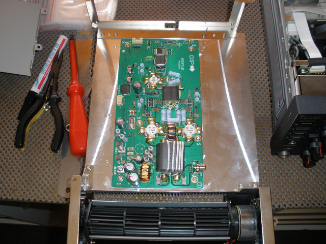
OK...you now have the PA Module out of the radio, so you can go to work changing the devices and checking over this board. Remove the metal cover. To check the two final devices, you can unsolder and lift the gate lead. Once it is free of the board, use a meter on a low ohms range to meter between the gate lead and the earth mat of the PA board...it should meter as an open circuit. If the devices are blown, you will see a dead short, or significant leakage. Remove both of the SD2931 devices, and then clean up the board pads so the new devices will sit nicely. You can now remove ALL the screws on the PA board, and the ones holding down the Driver. Lift the board up (you will have to apply a little force, as there are several rubber pads under the board that �stick� it down.) Once you have the board up, check all the underside for damage.
Pay particular attention to the 4 x 15Ω resistors up near the RF Output transformer, as they can be damaged when a device fails, and I have also found poor soldering in this area. Clean the heatsink with some denatured alcohol or thinners, and replace the insulating sheet and the board, after making sure that the Driver device has a nice thin coat of heatsink compound on its base. Tighten the board screws up nice and tight, then place the two new Final devices, making sure they also have a thin coat of heatsink compound on their bases. I have found two radios so far, that had quite loose device hold-down screws. Make sure you do these screws up tight...but don�t go overboard ! Use a well-fitting screwdriver. Finally, solder down the device leads, and then recheck your work.
 |
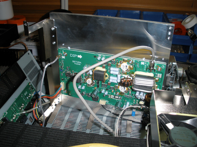
We are now ready to set the bias on the PA Board. You need to temporarily place the PA Module back into the radio, sitting in such a fashion that you can reconnect all the cables to the Module so it can be powered back up. At the same time, the Tuner Module needs to be temporarily plugged back in as well...the radio may function and allow you to set the bias without the Tuner Module in situ, but I did not test to see if this was the case. Reconnect the Tuner, and place it approximately in place, then place a sheet of cardboard between it and the fins of the PA Module, so the fins cannot accidentally contact any part of the Tuner Module. Note: The only cable that does not have to be reconnected is the + DC Supply to the PA Module...instead, insert an accurate DC ammeter in circuit, positive lead to the cable, and negative lead to the DC connect point on the PA Module.
Once you have all this setup, set the following pots on the PA Module fully CCW (max. resistance):
Coarse: R310, R407, R410.
Fine: R301, R425, R426.
Do not touch any other adjustments. Right...have a very good look around the radio to make sure you cannot see anything that is going to short out, and make sure the PA Module cannot fall over or move. I used a piece of coat-hanger wire to support the PA Module against the side of the radio so that it could not move. The Module will end up at about an 80� angle from the horizontal, with enough room for you to get to the bias adjust pots.
 |
Terminate ANT1 in a 50Ω load, and power up the radio. You should see 0.031mA or close to that on the ammeter. Place the radio into SSB Mode, turn the Mic Gain fully CCW, and set 14.100 on the display, USB. PTT the radio by pushing the TRANSMIT button. You should still see 0.031mA approx. Now, slowly adjust R310, and you will eventually see the current increase. Now do the fine adjustment on R301. You are looking for 150mA MORE than the resting reading of 0.031mA, i.e. approx. 181mA. Remove TRANSMIT and then reactivate it again, and confirm that you have approximately 181mA. Now, move to R407, and you are now looking for ...this is where it gets interesting...Motorola, in the data sheet specify 250mA IDQ. Icom specify 1000mA (1A). I would suggest 500mA as a safe, middle of the road setting.
So...you are now looking for 681mA as you adjust R407. Be careful, as you will turn the pot about three quarters of its travel before you will see a rapid increase in ID. Set 681mA with a fine adjustment on R425, recheck, then go on to R410 and R426. Use the same procedure, and you are now looking for 1.181A on the meter. So...the procedure is ....Standing current, plus 150mA, plus 500mA, plus 500mA. Once you have this, you are done!
Turn the radio off, remove the meter, and you are now ready to reassemble the radio. Replace the Positive DC lead to the board, and refit the metal cover. Remove the RF and Control cables from the rear of the PA Module (these can be plugged back in just before you replace the rear panel) and redress the front cables back where they came from on the end of the fan bracket. Refit the cable tie that holds those cables in place on the bracket. Replace the PA Module into the radio, and refit the four screws that hold the fan end of the PA Module. Refit the Tuner Module, carefully replacing the cables as you do so. Replace the two screws that hold down the front of the Tuner Module. Replace the radio side panel. Refit the speaker, and plug in the fan cable from the PA back into the connector that it came out of. Turn you attention to the rear of the radio. You can now refit the RF and Control cable into the rear of the PA. Make sure that the group of grey RF cables at the rear of the PA Module, closest to the Power Supply are BEHIND the bracket that is attached to the PA Module (and towards the front of the radio). Now, refit the flat ribbon cable to the antenna module, and hold the rear panel up against that module, and replace two screws to hold it in place. Now, refit the rear panel. It should easily go back into place. Replace ALL the screws carefully, and don�t over-tighten.
Replace the bottom cover, and then sit the radio on the bench, and carefully check over the internals, confirming that all cables are plugged back in, and nothing is caught or being squeezed between any brackets etc. Now, place a Wattmeter on ANT1, power up the radio, and make sure you have ANT1 selected. Place the radio into FM Mode on 14.100 MHz, set the power control to minimum, and press the TRANSMIT button. You should be greeted with about 3 Watts approx. Wind the control slowly to full power, and you should see approx. 200W. If all is well, refit the top cover, make sure all the case screws are tight, and that is it...the job is complete!
When you key the radio, with no drive, and the meter indicating ID, you should see an IDQ (resting current) of approx 1.2A...much reduced from the 3.5 � 4A that some radios had set for bias.