 |
 |
 |
Referring to Fig.1, the Drive Gain control (DRIV) varies the gain of the 455 kHz 2nd IF stage (Q501) in the exciter chain. This stage is outside the ALC loop. The Drive Gain control sets the power level of the signal entering the ALC loop at Q504, and thus sets the ALC control range. The RFALC line from the ALC comparator in the RF Unit applies ALC voltage to gain-controlled IF stages Q504 (455 kHz 2nd IF) and Q506 (64.455 MHz 3rd IF).
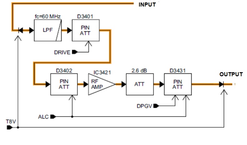
The Drive Gain feature in the IC-7610 is even simpler. Referring to Fig.2, the Drive Gain voltage (DRIVE) varies the insertion loss of PIN attenuator D3401 just ahead of, and outside the ALC loop. The Drive Gain voltage sets the power level of the signal entering the ALC loop at PIN attenuator D3402, and thus sets the ALC control range. The ALC line from the ALC block (Main Unit) applies ALC voltage to PIN attenuators D3402 and D3431, thus controlling the drive power.
 |
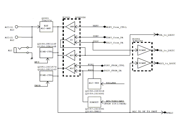
Referring to Fig.3, the RF Power control line (POCV) sets a voltage threshold which is compared to the forward-power voltage FORV_) from the reflectometer at the ATU input (on the CTRL Board). When the two voltages are equal, ALC voltage is developed. Thus, the RF Power setting determines the PA output. When the Drive Gain control is set for 30 - 50% ALC reading, the ALC loop will have sufficient loop gain to level the transmitter output with minimal overshoot, and the exciter will receive sufficient low-level drive to enable the RF Power control to set the power output. In addition, the reflected-power voltage (REFV_) from the reflectometer will develop ALC voltage, reducing drive in the event of a load mismatch (VSWR > 1.5:1).
If Drive Gain is too low, the driving power will be insufficient to drive the PA into ALC levelling. If it is too high, overshoot will occur until the ALC loop takes control. The overshoot will be of short duration, as the ALC attack time is very short. I am confident that even with some ALC overshoot, damage to the PA is unlikely.
It makes sense to set the Drive Gain on a band where the overall power gain is lowest, typically 10 or 6 metres. There will then be sufficient reserve to ensure proper (but not excessive) ALC action on the lower bands.
When the IC-7700 drives an external linear amplifier fitted with an ALC output, the ALC line from the amplifier (ALC) and the FORV_ line are summed at the ALC comparator (Q2001/IC2001). If the ALC voltage from the amplifier is higher than that of the exciter, it takes over and the exciter no longer controls the system power output.
 |
I adjust Drive Gain (DRIVE) in RTTY mode, with RF Power at 100W or 100%. A good-quality 50W resistive load is connected to the antenna port via an accurate in-line power meter.
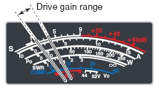
Typically, a Drive Gain (DRIVE) setting of 50% (12 o'clock) will yield an ALC scale reading in the range illustrated in Fig.4. This range is intended as a guideline, and is not critical; some band-to-band variation can be expected, as the power gain of the PA chain decreases on the higher bands. I have found that it is not necessary to readjust the Drive Gain control when changing bands.
Generally, the ALC reading should not exceed S9 (the top of the red zone on the ALC scale).
![]() The Drive Gain control is active for all modes other than SSB mode
with compression OFF. Therefore, when driving an external amplifier, it is
potentially unsafe to operate the IC-7700
with RF Power at 100% (fully clockwise) and then set the drive level to the amplifier
by adjusting Drive Gain. In the event that compression is turned off in SSB mode,
the amplifier will be overdriven and damage may result. This is especially true
when driving amplifiers not equipped with an ALC output.
The Drive Gain control is active for all modes other than SSB mode
with compression OFF. Therefore, when driving an external amplifier, it is
potentially unsafe to operate the IC-7700
with RF Power at 100% (fully clockwise) and then set the drive level to the amplifier
by adjusting Drive Gain. In the event that compression is turned off in SSB mode,
the amplifier will be overdriven and damage may result. This is especially true
when driving amplifiers not equipped with an ALC output.
When driving an amplifier without an ALC line, the RF Power control should be set to the level required to drive the amplifier to its rated power output. The Drive Gain control can then be backed off until the amplifier output just drops slightly. This will protect the amplifier from overdrive in the event that the IC-7700's RF Power control is inadvertently turned up to 100% in any mode except SSB with compression off. The above warning still applies for this case.
IC-7700 User Manual. p. 3-13, Drive Gain Adjustment.
IC-7610 Advanced User Manual, p. 9, Adjusting the Drive Gain level.
IC-7700 Service Manual, Block Diagrams, Pages 9-2 & 9-3.
IC-7610 Service Manual, Block Diagrams, Pages 8-1 through 8-3.
Copyright © 2010-2023, A. Farson VA7OJ/AB4OJ. Images courtesy Icom Inc. Last revised: 04/08/23.