 |
 |
On 27 August 2007, I ran an ALC overshoot test on my IC-756Pro3/Yaesu Quadra station as follows:
Frequency: 14140 kHz. Quadra Po = 1kW. Required drive power 70W.
Pro3 ANT1 ⇒ Bird 4273-025 line sampler ⇒ Bird 43 power meter ⇒ Quadra Input 1.
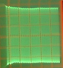
Sampling port of line sampler connected to Tektronix 455 oscilloscope Channel 1, terminated in 50Ω.
Scope set to 0.2V/div vertical, 0.1 sec/div horizontal.
Key exciter in USB mode, with Mic Gain fully CCW: no RF output; no spike.
Key exciter in RTTY mode: Drive drops off approx. 6% in first 100 mS, then settles.
Fig.1 illustrates what is happening. ALC settling time is approx. 100 mS, but there is no damaging overshoot.
In general, the initial ALC attack time should be as short as practicable, to minimise overshoot. For SSB service, the ALC decay time should be longer than the reciprocal of the syllabic rate (tdecay > 140 mS) to prevent the ALC from "riding" on voice peaks. For CW, the ALC decay time should be longer than the longest element at the slowest keying rate, to ensure that the ALC loop does not follow keying.
Looking at the ALC circuit in the Pro3 (IC551, Main Unit), the attack time (defined by R513, C504 + C506) is approx. 500 nS and the decay time (defined by R517, C504 + C506) is approx. 750 mS. (Ref. 1, p. 10-7). Other Icom exciters have similar ALC time constants.
When the ALC is correctly adjusted, it will level the system power gain to hold the CW or PEP output at the preset value.
It should be emphasised here that differing station configurations will yield widely divergent results. For instance, tube-type amplifiers with electronic bias switching (EBS) and/or frequency-sensitive ALC detectors may exhibit considerable overshoot and/or "sag". Long time constants in the ALC loop due to excessively high RC values can cause severe overshoot at the onset of RF drive. The amplifier, not the Icom exciter, is generally at fault in such cases.
Copyright © 2008 A. Farson VA7OJ/AB4OJ (including images). All rights reserved.
Last revised: September 25, 2019