 |
 |
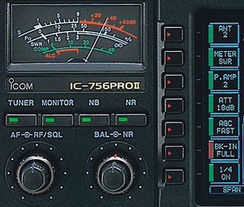
All superhet HF transceivers fitted with an antenna selector*, an RF gain control, an RF attenuator and an S-meter.
Antenna connected to ANT 1
ANT 2 terminated in 50Ω, or not connected (if ANT 1 and ANT 2 are both in use, terminate RX-ANT in 50Ω or leave it open.)
Preamp off
ATT = 0 dB
RF Gain at 100%
Tune off the signal and note S-meter reading on band noise alone (Example: S4).
Bring in sufficient attenuation (ATT) to reduce S-meter reading to S2 (ATT = 12 dB in this example).
Switch RX input from ANT 1 to ANT 2 (or ANT 1 to ANT 1/R).
Adjust RF Gain to raise S-meter reading from S0 to S2 (the reading obtained in Step 2 after attenuation was added).
Switch RX input back to ANT 1.
This procedure quiets down the background noise, but without degrading S/N.
By inserting 12 dB attenuation, we are reducing the band-noise/noise-floor margin from 12 dB to 0 dB. This is still acceptable, as we are degrading system NF only slightly if at all (provided that the margin remains positive.) The worst-case theoretical NF degradation is 3 dB.
Then, by setting RF Gain for an S2 reading, we raise the AGC threshold after attenuation (i.e. the input power level at which AGC starts levelling) from -96 to -90 dBm (3.5 to 7 µV). Now, the band noise will barely develop AGC voltage; almost all AGC action will be derived from the signal. As S/N is unchanged, the desired signal is pushed further down the receiver's transfer characteristic (S/N vs. C/N). Refer to the AGC gain-reduction curve.
The result is a much quieter receiver, but with no evident loss of sensitivity. We intend to study this further, and see how it works with weak DX signals as well as strong signals. The procedure appears to work best on 80m and 40m. We have not tried it on 160m.
The 3rd-order intercept point (IP3) increases by the amount of attenuation inserted. This is a very welcome secondary effect, without S/N penalty as long as the band-noise/noise-floor margin is 0 dB or greater.
Narrowing the IF passband will also cut the remaining noise level down noticeably.
* If the radio has only one antenna port (e.g. IC-7300), disconnect the antenna for Step 3, then reconnect it.
![]() Note:
For direct-sampling SDR transceivers and receivers
(IC-7300, IC-7610, IC-R8600) the procedure is even simpler:
Note:
For direct-sampling SDR transceivers and receivers
(IC-7300, IC-7610, IC-R8600) the procedure is even simpler:
Tune off the signal and note S-meter reading on band noise alone (Example: S6).
Turn down RF Gain (RFG indicator will light) and/or insert attenuation until band noise just deflects the S-meter, and is barely visible on the spectrum scope and waterfall.
Tune in the signal again. Band noise will not stimulate AGC action; this will allow the AGC to operate only on the signal.
This is the optimum operating point for the receiver. On 7 MHz and below, the band noise can be as much as 12-15 dB above the receiver's noise floor.
| Note contributed by
Matt, KK5DR: When operating CW with IF
filter bandwidths in the 50 to 250 Hz range, slight
DSP artifacts can sometimes be heard. These sound
like cellophane being crinkled, and are caused by
DSP processing of band noise. Changing AGC settings
has little effect on this. Using the above method, decrease RF gain to the point where only the desired CW signal is audible. At this point, the artifacts will be almost inaudible. Start by reducing the RF gain, then try various combinations of RF attenuator and pre-amps. This will redistribute the gain in the front end. This method worked nicely for me. I was able to fully copy a CW signal which did not register on the S-meter to begin with, and I was able to still copy it very well with the RF gain setting the S-meter at S9 + 20dB and 18dB of attenuation engaged. The "cellophane" sound was gone. I hope this procedure helps you obtain clean CW copy. |
Link: IC-756Pro II S-Meter & Spectrum Scope Calibration Curves
Note: S/N will be degraded if the added attenuation exceeds the band-noise/noise-floor margin (ATT > 12 dB).
Reference: "HF Radio Systems & Circuits", Sabin & Schoenike, editors. Noble, 1998, Chapter 1, Section 1.4, pp. 8-10.
Acknowledgements: We are indebted to our friend Andrew Roos, ZS6AA, for his constructive contributions to this article.
Copyright © 2004-2014 A. Farson VA7OJ/AB4OJ and George T. Baker W5YR. All rights reserved.
Last updated: 09/25/2019