Audio Image, and Filter Bandwidth Settings, in the 756Pro/Pro2/Pro3
by Adam Farson VA7OJ/AB4OJ
1. Introduction: Recent discussion of the received audio image in conjunction with the CW offset led me to a further investigation: What happens if the SSB filter bandwidth is set equal to, or greater than, twice the difference between virtual carrier and passband centre?
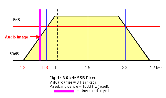
The SSB passband centre is offset 1500 Hz from virtual carrier; this offset is fixed, and does not vary with Twin PBT setting. Thus, with BW = 3.6 kHz, it is apparent that there will be a strong audio image, as the lower corner of the passband (the lower -6 dB point) is at -300 Hz (virtual carrier = 0 Hz).
I set BW = 3.6 kHz, and the [FILTER] graphic display confirmed this.
2. SSB Tests: Using the internal cal marker as a signal source, I tuned the VFO to 7100.000 kHz LSB. At zero-beat (7100.000), the marker was S9+15 dB. At 7099.575 kHz (-425 Hz), the audio image was still S9. The audio image only became inaudible at -1000 Hz.
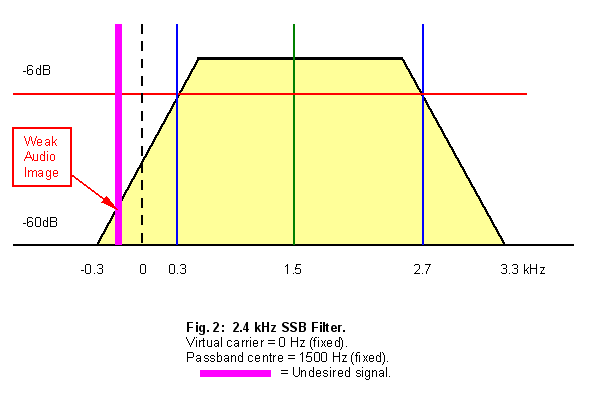
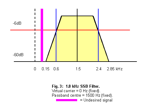
Figures 1 through 3 illustrate the frequency and amplitude relationships involved. Consider the case of the 3.6 kHz filter. If the -300 Hz point on the x-axis is, in fact, the lower -6dB point on the y-axis, and the filter shape factor is 1.5 (per the Pro2 specs), then the lower -60dB point is at -1.2 kHz. This will pass the audio image.
By the same reasoning, for the 2.4 kHz filter, with the lower -6dB point at +300 Hz, the lower -60 dB point is at -300 Hz. For the 1.8 kHz filter, with the lower -6dB point at +600 Hz, the lower -60 dB point is at +150 Hz.
The cal marker is quite strong; S9+15 dB is (theoretically) -57 dBm if we assume that S9 = 50 µV, whilst the MDS is -132 dBm. Thus, the DSP filter stopband attenuation is at least 75 dB.
Note: Shifting the lower flank of the filter passband UP via Twin PBT will reduce or eliminate the audio image, but at the expense of reduced low-frequency audio response.
| 3.6 kHz SSB Filter | |
|---|---|
| VFO offset from zero-beat | Signal strength |
| 0 Hz | S9 + 15 dB |
| -425 Hz | S9 (strong audio image) |
| -1000 Hz | No longer audible |
| 2.4 kHz SSB Filter | |
|---|---|
| VFO offset from zero-beat | Signal strength |
| 0 Hz | S2 |
| -200 Hz | Audible, but no S-meter reading |
| -450 Hz | No longer audible |
| 1.8 kHz SSB Filter | |
|---|---|
| VFO offset from zero-beat | Signal strength |
| 0 Hz | No S-meter reading |
| -100 ~ -150 Hz | Not audible, no S-meter reading |
| -150 ~ -230 Hz | "Comeback", just audible |
| < -230 Hz | No longer audible |
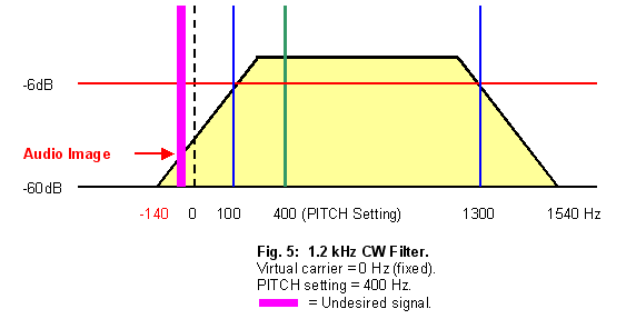
3. CW Tests: At the suggestion of George W5YR, Iran a CW test case on theIC-756Pro2, again with the cal marker as signal source. I took 6 scenarios; BW = 1.2 kHz, 500 Hz and 250 Hz, each with 600 Hz (default) and 400 Hz pitch.
The IF-DSP filters for CW are generated to be centred*on the CW pitch frequency selected via the PITCH control, and the receiver tuning is always offset from the received signal to produce a beat note exactly equal to the PITCH setting.
The operation of the CW Pitch control is interesting. As in the SSB case,
the virtual carrier is fixed. The effect of the Pitch control is to shift the
filter passband, and thus the CW offset, with respect to virtual carrier. This has
the same effect as shifting the virtual carrier, except that the receive
frequency does not change.
"Pitch" is the 756Pro/Pro2/Pro3 CW Pitch setting. When the VFO is tuned to the virtual carrier frequency of
the transmitted signal (actual frequency - CW offset), the recovered audio
frequency is equal to the "Pitch" setting. (Note: The transmit sidetone frequency tracks the "Pitch" setting, but rotating the "Pitch" control does not vary the actual transmit frequency.)
"VFO offset" is defined here as the displacement of the received signal from virtual carrier.
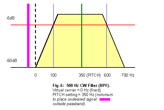
The IC-756Pro/Pro2/Pro3 specifications give a shape factor of 1.4 for the CW filters (BPF indicator lit). For the 500 Hz filter, with the lower -6dB point at +350 Hz, the lower -60 dB point is at -250 Hz. For the 250 Hz filter, with the lower -6dB point at +475 Hz, the lower -60 dB point is at +425 Hz.
Figures 4 through 6 illustrate the frequency and amplitude relationships involved in the CW tests.
*See Note on 1.2 kHz CW filter below.
Read Greg, W8WWV's IC-756Pro CW Filter Shape Selection Page.
| 1.2 kHz CW Filter, Pitch = 600 Hz | |
|---|---|
| VFO offset from virtual carrier | Signal strength |
| +600 Hz | S9 + 15 dB |
| +200 Hz | S9 +5 dB |
| +100 Hz | S7 |
| 0 Hz | S2.5 |
| -200 Hz | <S1 |
| -300 Hz | S0, audible |
| -400 Hz | S0, just perceptible |
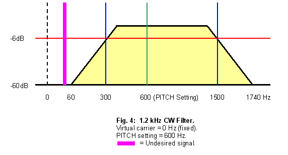
Note: It will be seen that the 1.2 kHz CW filter is asymmetrically disposed about the 600 Hz (default) Pitch reference line. The [FILTER] graphic display confirms this. The reason for the asymmetry is to accommodate the ±300 Hz range of the Pitch control, whilst ensuring adequate audio-image suppression at Pitch settings of 600 Hz and higher.
| 1.2 kHz CW Filter, Pitch = 400 Hz | |
|---|---|
| VFO offset from virtual carrier | Signal strength |
| +400 Hz | S9 + 15 dB |
| 0 Hz | S9 + 5 dB |
| -200 Hz | S2 (strong audio image) |
| -400 Hz | <S1 |
| -500 Hz | S0, audible |
| -600 Hz | S0, just perceptible |
The S2 audio image with BW = 1.2 kHz, Pitch = 400 Hz and VFO offset = -200 Hz is what one correspondent heard when he suspected poor opposite-sideband suppression.
For BW = 500 and 250 Hz, as expected, there was no audio image with either of the two
offsets tested (600 and 400 Hz).
Fig. 6 shows that for the case of the 500 Hz filter, 350 Hz is the minimum Pitch setting which will place an undesired signal outside the filter passband and ensure that no audio image will be heard.
4. Conclusion: Icom's DSP designers have provided the IC-756Pro/Pro2/Pro3 user with an unprecedented set of IF passband management tools. Using the Filter menu, with its continuously-variable bandwidth settings, the Twin PBT, Manual Notch and CW Pitch controls, the operator can configure the receiver IF passband and CW tone to suit virtually any set of band and operating conditions.
This great flexibility carries with it the risk that certain combinations of settings can create undesired effects, such as the audio image discussed above. The intent of this page is to assist the operator in exploiting the Pro/Pro2/Pro3 to the full, whilst avoiding such pitfalls. (The above information is also applicable to the IC-7850/7851, IC-7800, IC-7700, IC-7600, IC-746Pro, IC-7400, IC-7200, IC-7410, IC-9100, IC-7100, IC-7000, IC-7300, IC-9700, IC-705 and IC-7610.)
It should be noted that another manufacturer uses a different approach in its DSP-IF radios to avoid this image problem. As the bandwidth is increased, the bandwidth-control software halts and freezes the lower passband edge at zero, and moves only the upper edge higher as the bandwidth is increased. Thus, the image situation can never arise.
Although their solution eliminates this subtle trap for the unwary, it does so at a slight cost in flexibility.
Copyright © 2002-2022 A. Farson VA7OJ/AB4OJ (including all images). All rights reserved. Last updated 10/20/19