The ZS6XT Hybrid 20m SSB/CW Transceiver (1964) |
|---|
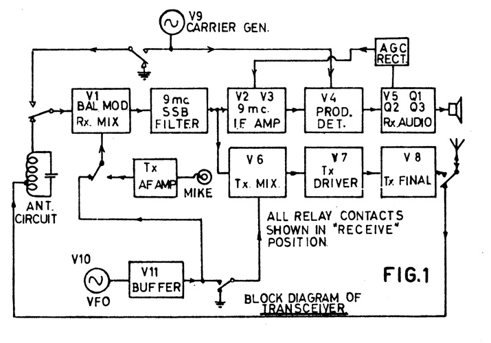
| I started the design in January 1964. Working evenings and weekends, the project took 6 months to complete. The architecture of this radio was unique, in that the RCA-7360 beam-deflection mixer was dual-function; receiver front-end, and transmitter balanced modulator. On receive, the preselector output was applied to the grid, and the local oscillator to the deflection plates. On transmit, the 9 MHz carrier was applied to the grid, and the mike audio to the deflection plates. (See block diagram below). This approach kept the tube count to 11. The receiver audio output stage, AGC/S-meter circuit, VOX and transmitter speech amplifier were solid-state. |
| Further Reading |
|
 |
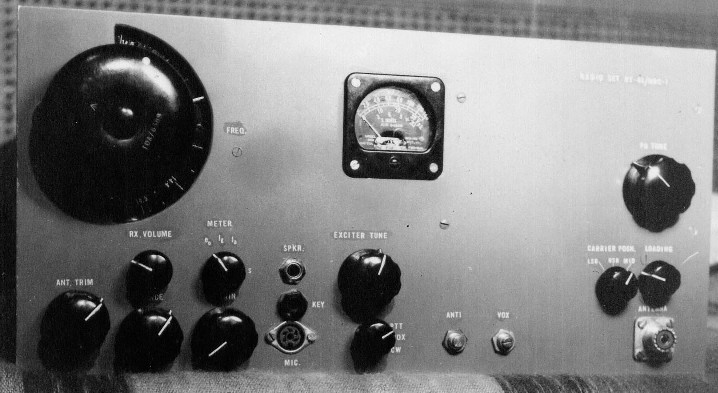
| Front panel. Main tuning dial (Muirhead vernier) & receiver controls at left, driver tuning at centre, PA tuning & loading at right. |
 |
| Block Diagram of Transceiver |
| Note that the ANT. CIRCUIT was a single-tuned circuit, parallel-resonant at 14 MHz and series-resonant at the 4 MHz image frequency. This ensured adequate image rejection. |
| 20m SSB/CW Transceiver Tube Complement: |
| V1 7360 Rx Mixer/Tx Bal Mod V2 EF183 (6EH7) 1st IF Amp V3 EF89 (6DA6) 2nd IF Amp V4 ECC82 (12AU7) Prod Det (later replaced by 7360)* V5 ECC81 (12AT7) 1st AF Amp V6 ECC81 (12AT7) Tx Mixer V7 EL83 (6CK6) Tx Driver V8 QQE06-40 (5894) Tx PA (selected for its excellent linearity) V9 ECC81 (12AT7) 9 MHz Carrier Gen V10 EF91 (6AM6) 5 ~ 5.5 MHz VFO V11 ECF89 (6U8) VFO Bandpass Buffer/Cathode Follower |
| * It was determined that extremely strong received signals ( > 200 mV) outside the passband of the 9 MHz IF crystal filter were blowing by the filter's 60 dB stopband attenuation, and causing cross-modulation in the 12AU7 product detector. A redesigned product detector, using a second 7360, corrected this problem. |
| Performance Specifications: |
| General: |
| Frequency Range 14.000 - 14.500 MHz Modes: USB, LSB, CW |
| Receiver: |
| Sensitivity: 0.2 µV (-122 dBm) for 10 dB (S+N)/N MDS = -132 dBm (50Ω) Noise figure (measured): 4.3 dB at 14250 kHz, with 2.7 kHz IF bandwidth Selectivity: 2.7 kHz @ -6 dB, 3.9 kHz @ -55dB Image rejection: Better than -60 dB Spurious responses: -80 dB Cross-modulation dynamic range: 94 dB referred to a -101 dBm desired signal at 25 kHz offset and 2.7 kHz IF bandwidth (astounding for that era!) |
| Transmitter: |
| Power output: 65W PEP, 65W CW into 50 Ω Carrier suppression: -60 dBc Unwanted-sideband suppression: -55 dBc Spurious signals: Better than -50 dBc 3rd-order intermodulation products: -37 dBc (43 dB below 2-tone PEP) at 65W PEP output |
 |
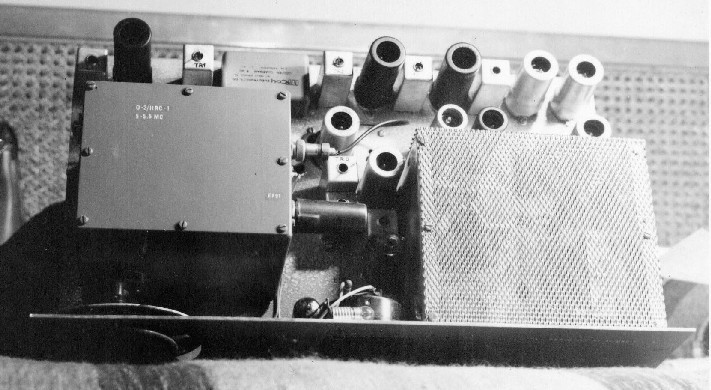
| Top view of chassis, with VFO on left and PA cage on right. Note 7360 tube & 9 MHz crystal filter at left rear. |
 |
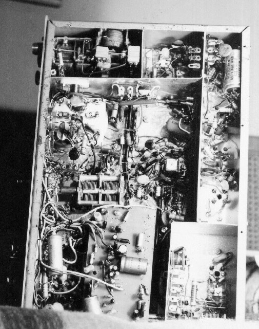
Underside of chassis. |
| Note 7360 mixer compartment at bottom right, IF strip at right, audio/VOX board & exciter tuning capacitor at centre, and antenna relay at top left, with PA tube socket just below it. |
| The material on this page is excerpted from an article I published in "Radio ZS" , October, 1964. |
| Copyright © A. Farson 2001-2019 (including photos). All rights reserved. |
| Last revised: July 28, 2021. |
| |